Phase-Locked Loop
Introduction
A Phase Lock Feedback Loop block diagram can be seen in the figure below.
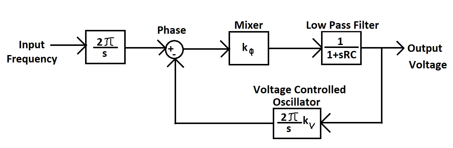
The value of R is 100k, the value of k:phi is 1.5, and the value of k:v is 10^4. Three different capaitor values were used later in the lab.
A feedback loop is defined as when the output of a system also is used as an input to the system. This type of system has many types of applications such as a thermostat, vehicle cruise control, or any kind of pressure regulators such as a steam regulator. A feedback system can be very complicated, but they can be simplified into a single transfer function in order to be studied. A transfer function is given in the frequency domain, and transforms a single input into an output. J.B.
A feedback loop is defined as when the output of a system also is used as an input to the system. This type of system has many types of applications such as a thermostat, vehicle cruise control, or any kind of pressure regulators such as a steam regulator. A feedback system can be very complicated, but they can be simplified into a single transfer function in order to be studied. A transfer function is given in the frequency domain, and transforms a single input into an output. J.B.
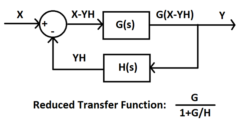
The figure above shows the Feedback Loop block diagram. G(s) and H(s) are functions in the frequency domain, the Reduced Transfer Function can be seen and is equal to y/x.


The above images are taken from the schematics and spec sheets of the CD4046B IC chip. This chip is a Phase Lock Loop chip which is what was used in the lab exercises below. The schimatic and the associated graphs are important to help better understand the function operation of the chip.
Laboratory Work


The PLL circuit shown above was used with three different capacitor sizes. A 3392 pF, 516 pF, and a 34 pF capacitor were used. The images below show the center frequency sweeps and scope of the VCO sensitivities for each different capacitor.
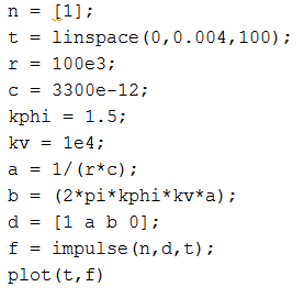
Matlab was used to graphically represent the frequency response of the PLL System for the three different capacitors.
PLL Demodulations below.


Reference Sites
